Worldwide Sites
You have been detected as being from . Where applicable, you can see country-specific product information, offers, and pricing.
Keyboard ALT + g to toggle grid overlay
Why choose Arnold for Houdini?
Brute force to render whatever you need
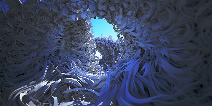
No matter how complex or heavy your scene, Arnold has the strength to handle it. It thrives on large datasets, so you can render without ever having to worry about a breakdown.
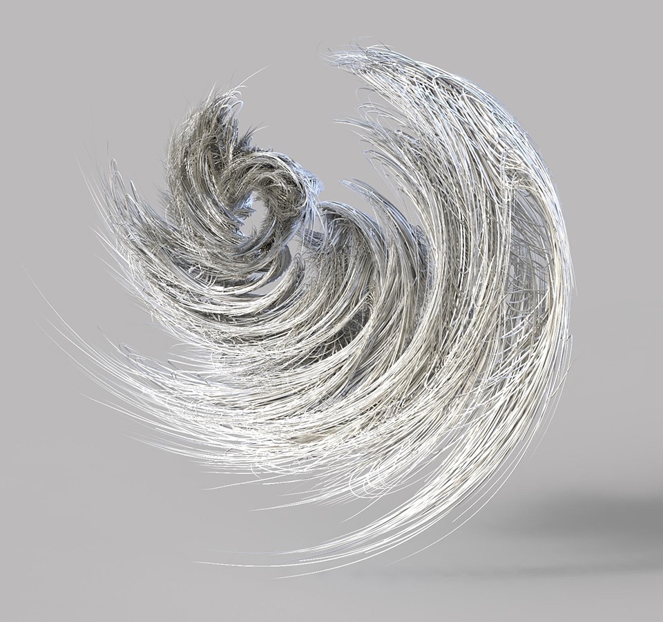
Image courtesy of Heribert Raab
Smooth integration with Houdini
The Arnold plugin for Houdini (HtoA) is specially crafted for the needs of Houdini artists. Designed to feel like a native part of Houdini, HtoA supports all of the unique functionality you rely on – including new support for Solaris, saving you time and helping you work more efficiently.
The power to choose
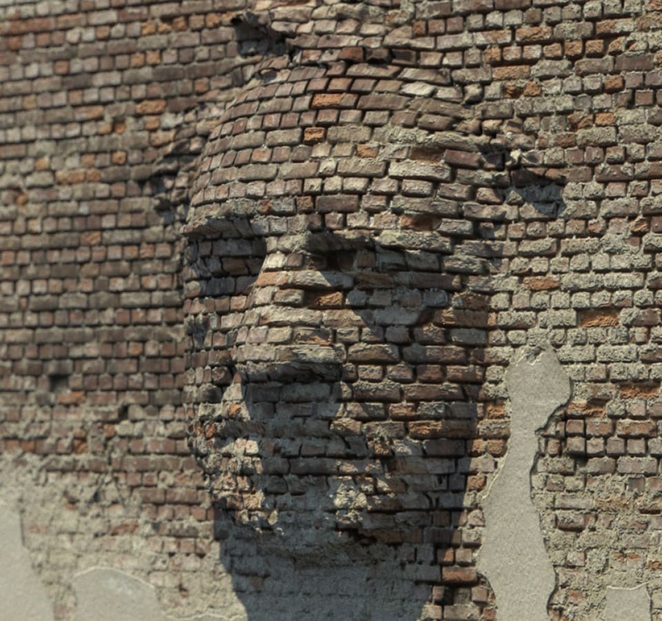
Pick and choose when you need to use CPU or GPU rendering. Iterate quickly on assets using the GPU renderer, then flip over to CPU rendering when you need to scale up and render your heavier scenes.
Open and extensible architecture
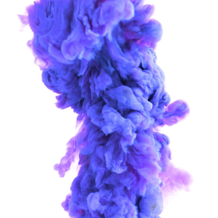
Get the scalability of an open architecture that makes it easy to integrate Arnold into your pipeline and adapt to project needs. Create custom cameras, light filters, output drivers, and shaders.
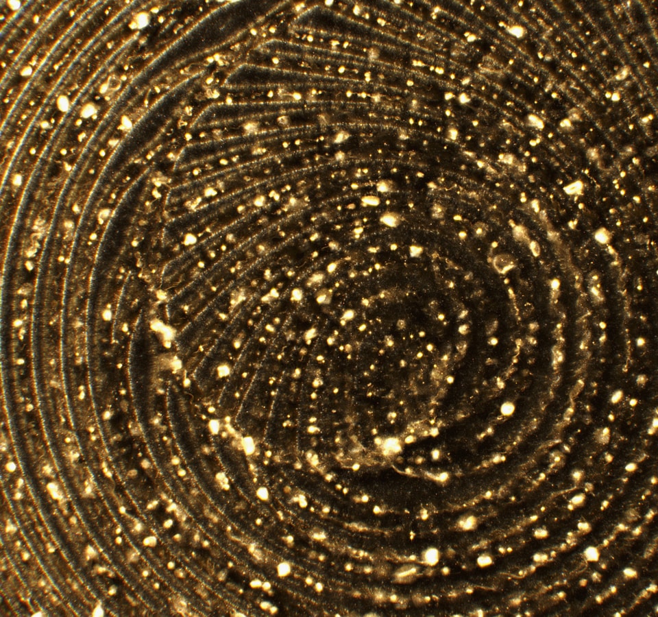
Image courtesy of Serjan Burlak
Features ‘for days’
HtoA supports Arnold’s full feature set with tools built to give you more control over lights, shaders, and other render effects, including:
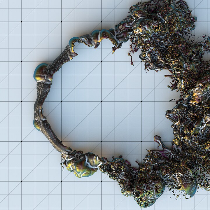
- Shading Network Editor: Write custom shaders and create unique effects like the Volume Displacement technique.
- Custom AOV’s (Arbitrary Output Variables or passes): Render any number of AOVs or passes for compositing purposes, including normal, Z-depth, position and ID masks.
- Alembic procedurals: Render Alembic files directly without any translation.
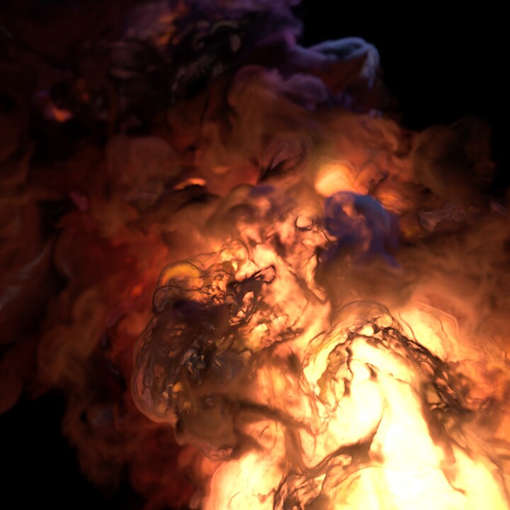
- High-quality volumetric rendering: Render complex effects such as smoke, clouds, fog, pyroclastic flow, and fire.
Powerful tools give you more control over render effects:
- Shading Network Editor
- Custom AOV’s (Arbitrary Output Variables or passes)
- Alembic procedurals
- High-quality volumetric rendering
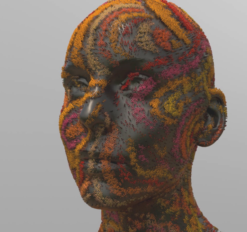
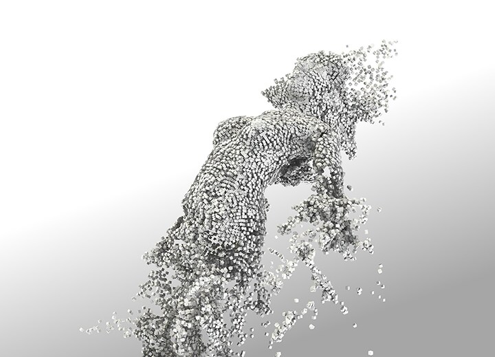
Image courtesy of Yasin SINIK
Under the hood
Rendering volumetric fractals with OSL
-
Under the hood
Rendering volumetric fractals with OSL
Juraj Tomori
Computer artist
This tutorial will show you how to create volumetric fractal scenes with the help of Open Shading Language (OSL). It will take you through a process of setting up simple scenes, defining fractal scenes in shaders with OSL and optimizing render settings.
By the end of the tutorial, you should be able to produce similar results.
-
Under the hood / Sphere shader
In this example, we will define the rendered scene in a shader, which will output density values for each shaded sample. To render volumes in specified bounds we can create a box and render it as a volume.
Follow step-by-step instructions
In this example, we will define the rendered scene in a shader, which will output density values for each shaded sample. To render volumes in specified bounds we can create a box and render it as a volume.
-
Under the hood / Mandelbulb Fractal
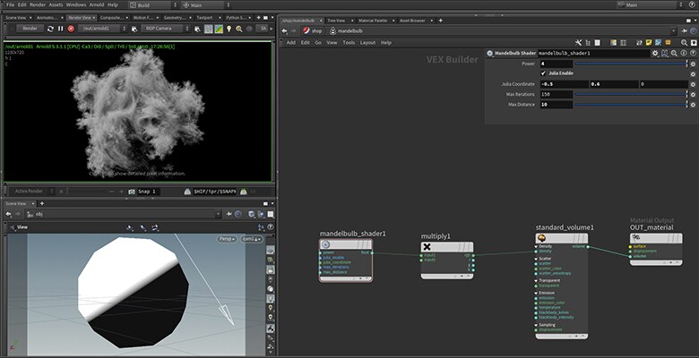
Now that we know how to define shapes in OSL we can move on to more interesting shapes. Mandelbrot fractal is defined in a 2D complex plane; Mandelbulb fractal is defined in 3D space. Mandelbrot is not defined in 3D, but Mandelbulb results in a nice shape and is inspired by Mandelbrot.
Follow step-by-step instructions
Now that we know how to define shapes in OSL we can move on to more interesting shapes. Mandelbrot fractal is defined in a 2D complex plane; Mandelbulb fractal is defined in 3D space. Mandelbrot is not defined in 3D, but Mandelbulb results in a nice shape and is inspired by Mandelbrot.
-
Under the hood / Emissive Mandelbulb Fractal
So far we were able to create nice shapes but they are all grey. Let's try to bring in some colors with a technique called orbit traps. This shader will have five different orbit traps.
Follow step-by-step instructions
So far we were able to create nice shapes but they are all grey. Let's try to bring in some colors with a technique called orbit traps. This shader will have five different orbit traps.
-
Under the hood / Fractal Quality Settings
Two options control the amount of detail in our volumetric scene: volume Step Size on the bounding box object, and the size and shape of the bounding geometry. There are also standard Arnold ROP quality settings.
Learn more about fractal quality settings
Two options control the amount of detail in our volumetric scene: volume Step Size on the bounding box object, and the size and shape of the bounding geometry. There are also standard Arnold ROP quality settings.
-
TutorialSphere shader
Let's start with a simple example to show the technique. In this example, we will define the rendered scene (sphere in this case, but fractals later on) in a shader, which will output density values for each shaded sample. To render volumes in specified bounds, we can create a box and render it as a volume.
- Start by creating a box with Uniform Scale set to 2. Set the volume Step Size to something larger than 0 (for example 0.1) to render the mesh as a volume.
- Create an Arnold ROP, camera and a light to view the results.
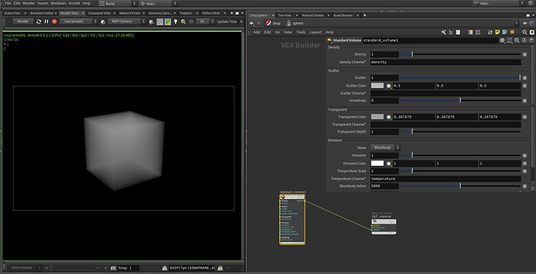
- Create a shader with Standard Volume connected to the Volume slot in the Material Output node.
- Press the Render button in the Render View pane. You should see a volumetric cube being rendered.
Now we have a boilerplate to play around with the shader, which will define our shape. The current setup outputs uniform density everywhere in our box bounds, which results in a box. Let's try something slightly more interesting—a sphere. In our case, a spherical volume can be defined as an implicit volume like this: Every point which distance to the center is smaller or equal than the sphere's radius is dense. The rest is empty. This definition could be rewritten in the following pseudo-code:
if (length(P_world) <= sphere_radius)
    density = 1
else
    density = 0
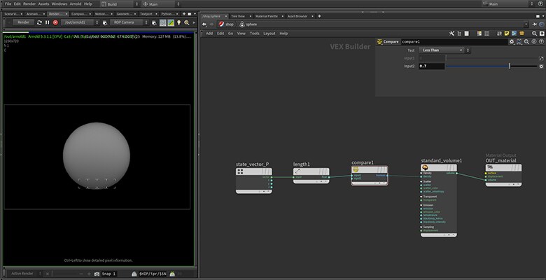
Where P_world is the world space position of a shaded sample and length() returns Euclidean length of a vector. This can be translated into the following shading network. State Vector is outputting Shading Point in World-Space P and Compare node is set to Less Than or Equal than the sphere's radius.
We managed to define a shape only by using shading nodes, but we could get more control if we could define our shape programmatically - like in our pseudo-code. In fact, this can easily be done with the help of OSL. Let's try to re-create our sphere in OSL to see how our shading network will change. In our case the sphere shader will look like this:
sphere_shader.osl
shader sphere_shader(
    float sphere_radius = 1.0,
    output float density = 0.0
)
{
    if (length(P) <= sphere_radius)
        density = 1.0;
    else
        density = 0.0;
}
sphere_shader is the name of our shader. float sphere_radius defines the node's parameter with its default value, output float defines the type of node's output and P is a global variable provided by Arnold. As you can see the OSL code closely matches our pseudo code above.
Save sphere_shader.osl somewhere and set the ARNOLD_PLUGIN_PATH environment variable pointing to a folder where this shader is located. For example, you can specify it in your houdini.env file:
ARNOLD_PLUGIN_PATH = /path/to/folder/with/osl/shaders
After you set the path to shaders, you should see it in SHOPs after restarting Houdini.
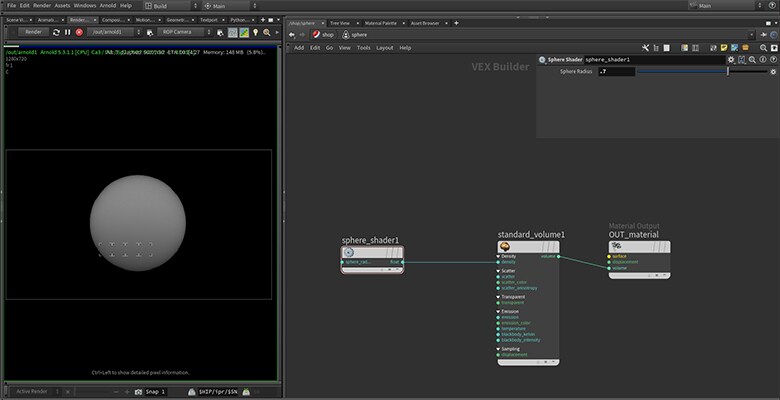
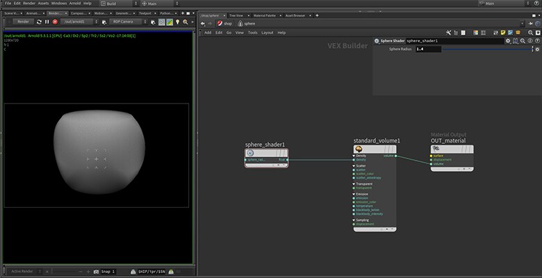
As you can see the network is much simpler now and provides us with an identical result. Note that you need to restart Houdini only if you create a new shader or you modify shader's output or input parameters. Changes to the OSL code don't require Houdini's restart and will be reflected after the next press of the Render button. If you play with the sphere's radius you might sometimes get results as in the picture below. This means that your sphere is larger than your bounding object and you need to adjust the size of the sphere or bounding object.
-
TutorialMandelbulb fractal
Now that know how to define shapes in OSL we can move on to more interesting shapes. Mandelbrot fractal is defined in a 2D complex plane, where each sample is iteratively evaluated and tested if it shoots off to infinity, or stays bounded. Mandelbulb fractal is defined in 3D space constructed by Daniel White and Paul Nylander. Mandelbrot is not defined in 3D, but Mandelbulb results in a nice shape and is inspired by Mandelbrot. Let's create a new OSL shader and do small modifications to our scene.
mandelbulb_shader.osl
shader mandelbulb_shader(
    float power = 8.0,
    int julia_enable = 0 [[ string widget = "boolean" ]],
    vector julia_coordinate = vector(0, 0, 0),
    int max_iterations = 150,
    float max_distance = 20.0,
    output float density = 0
)
{
    point P_in = P;
    point Z = P;
    int i;
    for (i = 0; i < max_iterations; i++)
    {
        float distance = length(Z);
        // convert to polar coordinates
        float theta = acos(Z[2] / distance);
        float phi = atan2(Z[1], Z[0]);

        // scale and rotate the point
        float zr = pow(distance, power);
        theta *= power;
        phi *= power;

        // convert back to cartesian coordinates
        point new_Z = zr * point( sin(theta)*cos(phi), sin(phi)*sin(theta), cos(theta) );
        // update our point in normal or julia mode
        if (julia_enable == 0)
        {
            Z = new_Z + P_in;
        }
        else
        {
            Z = new_Z + julia_coordinate;
        }
        distance = length(Z);
        if (distance > max_distance) break;
    }
    // define density: 1 where point did not escape, 0 where point escaped to infinity
    if (i == max_iterations)
        density = 1.0;
    else
        density = 0.0;
}
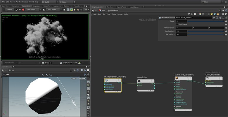
Reload your Houdini scene and drop the new Mandelbulb Shader node to the shading network. Change bounding geometry from box to a sphere, so that our shape is better contained and rendering is more efficient. Create a Multiply node to increase density, since our shader outputs only 1 or 0.
Play around with the Power parameter and try Julia mode by enabling Julia enable and setting different Julia Coordinates. You can animate the parameters to create interesting animated shapes.
-
TutorialEmissive Mandelbulb fractal
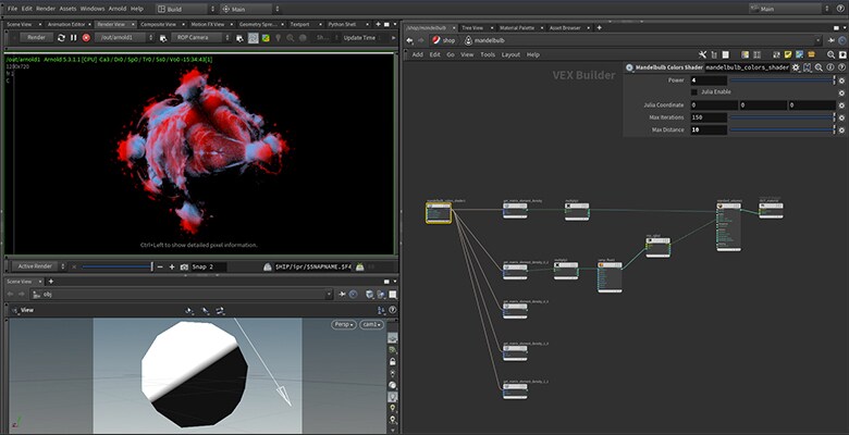
So far we were able to create nice shapes but they are all grey. Let's try to bring in some colors with a technique called orbit traps. The following shader has five different orbit traps. It also includes two helper functions: length2() and distPointPlane().
mandelbulb_colors_shader.osl
// squared length
float length2(vector vec)
{
    return dot(vec, vec);
}
// point to plane distance
float distPointPlane(vector pt, vector plane_n, vector plane_point)
{
    float sb, sn, sd;
    vector point_proj;
    sn = -dot( plane_n, (pt - plane_point));
    sd = dot(plane_n, plane_n);
    sb = sn / sd;
    point_proj = pt + sb * plane_n;

    return length(pt - point_proj);
}
shader mandelbulb_colors_shader(
    float power = 8.0,
    int julia_enable = 0 [[ string widget = "boolean" ]],
    vector julia_coordinate = vector(0, 0, 0),
    int max_iterations = 150,
    float max_distance = 20.0,
    output matrix out = 0
)
{
    point P_in = P;
    point Z = P;
    int i;
    // orbit traps
    float orbit_coord_dist = 100000;
    float orbit_sphere_dist = 100000;
    point orbit_plane_origin = point(0.0);
    vector orbit_plane_dist = vector(100000);
    for (i = 0; i < max_iterations; i++)
    {
        float distance = length(Z);
        // convert to polar coordinates
        float theta = acos(Z[2] / distance);
        float phi = atan2(Z[1], Z[0]);

        // scale and rotate the point
        float zr = pow(distance, power);
        theta *= power;
        phi *= power;

        // convert back to cartesian coordinates
        point new_Z = zr * point( sin(theta)*cos(phi), sin(phi)*sin(theta), cos(theta) );
        // update our point in normal or julia mode
        if (julia_enable == 0)
        {
            Z = new_Z + P_in;
        }
        else
        {
            Z = new_Z + julia_coordinate;
        }
        distance = length(Z);
        if (distance > max_distance) break;
        // orbit traps
        orbit_coord_dist = min(orbit_coord_dist, fabs( length2(Z - P_in) ));
        orbit_sphere_dist = min( orbit_sphere_dist, fabs( length2(Z - point(0)) - 2.0) );
        orbit_plane_dist[0] = min( orbit_plane_dist[0], distPointPlane(Z, vector(1.0, 0.0, 0.0), orbit_plane_origin) );
        orbit_plane_dist[1] = min( orbit_plane_dist[1], distPointPlane(Z, vector(0.0, 1.0, 0.0), orbit_plane_origin) );
        orbit_plane_dist[2] = min( orbit_plane_dist[2], distPointPlane(Z, vector(0.0, 0.0, 1.0), orbit_plane_origin) );
    }
    // orbit traps
    orbit_coord_dist = sqrt(orbit_coord_dist);
    orbit_sphere_dist = sqrt(orbit_sphere_dist);
    // define density: 1 where point did not escape, 0 where point escaped to infinity
    float density;
    if (i == max_iterations)
        density = 1.0;
    else
        density = 0.0;

    // output values
    out[0][0] = density;
    out[0][1] = orbit_coord_dist;
    out[0][2] = orbit_sphere_dist;
    out[0][3] = orbit_plane_dist[0];
    out[1][0] = orbit_plane_dist[1];
    out[1][1] = orbit_plane_dist[2];
}
Note that currently there is a limitation which enables us to have only a single output in an OSL node. To work-around it, we can output a matrix type, which consists of 16 float values (4x4 transformation matrix). To output multiple values from a single node we can pack our values in a matrix and extract them in the shading network with the following helper OSL shader.
get_matrix_element.osl
shader vft_get_matrix_element(
    matrix mat = 1,
    int row = 0,
    int column = 0,
    output float element_out = 0.0
)
{
    element_out = mat[row][column];
}
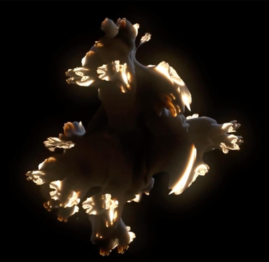
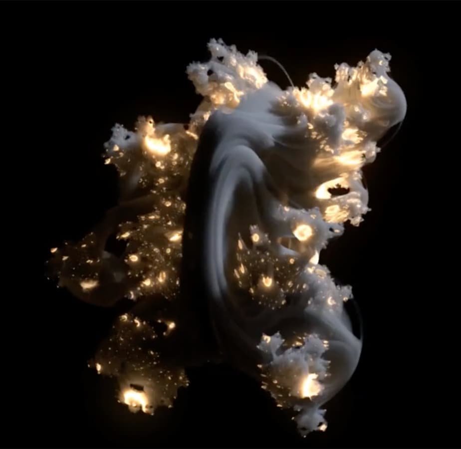
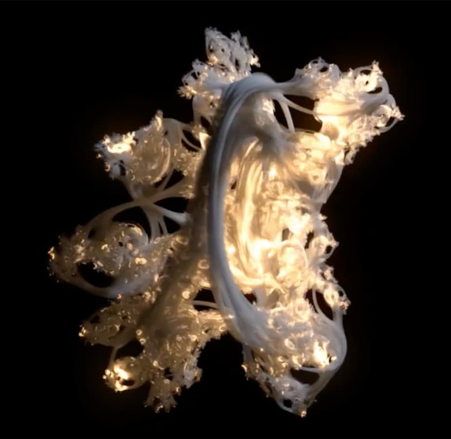
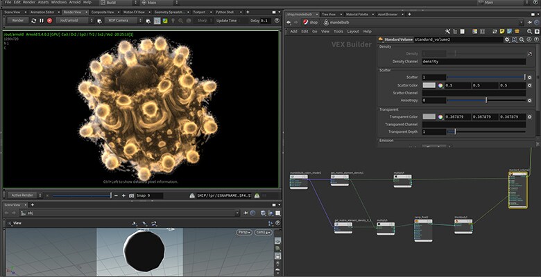
Based on the Mandelbulb shader we can use the same indices to extract the values and use them in shading. There comes your creativity to play around with values, combine them and produce visually interesting images. In the following image, an orbit trap was used for mixing two different colors which are driving Scatter Color parameter in the Standard Volume node.
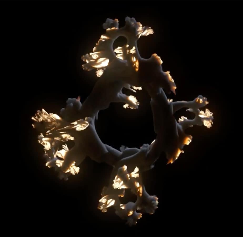
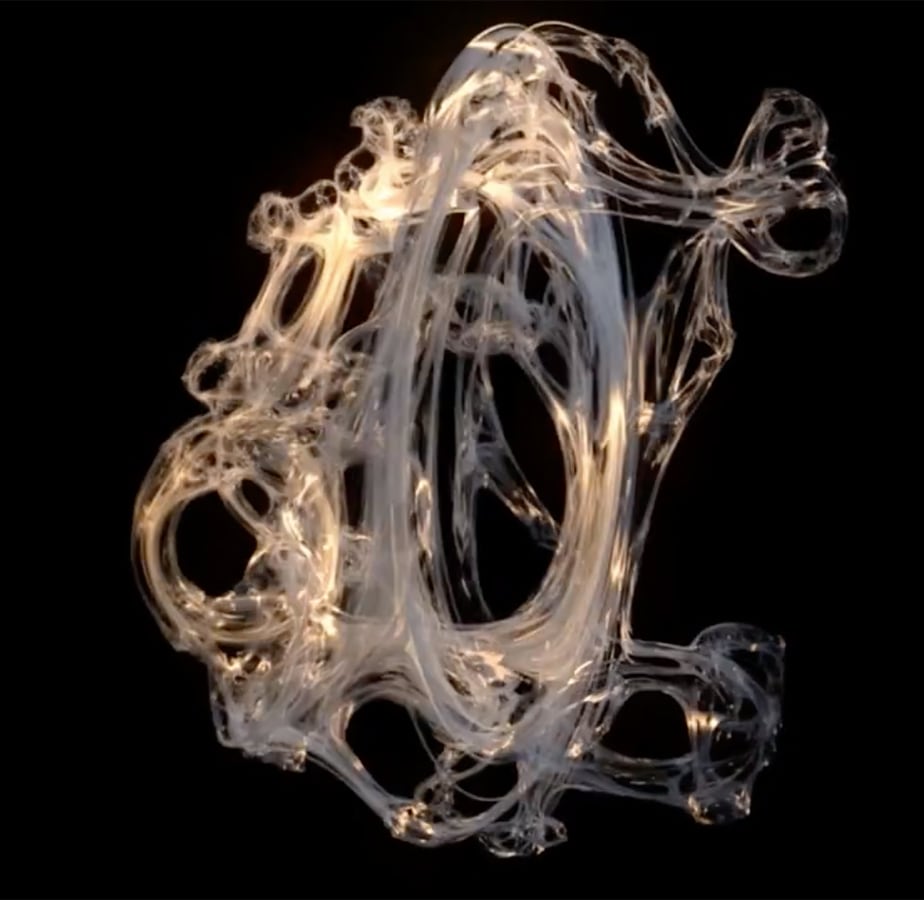
In the following image, an orbit trap was used to drive Blackbody radiation of the volume.
-
Learn moreFractal quality settings
The first option which controls the amount of detail in our volumetric scene is volume Step Size on the bounding box object. The smaller the number the more detail will be in the rendered volume. Try setting it to lower values until you don't see a difference. Setting it too low will have a negative impact on render times.
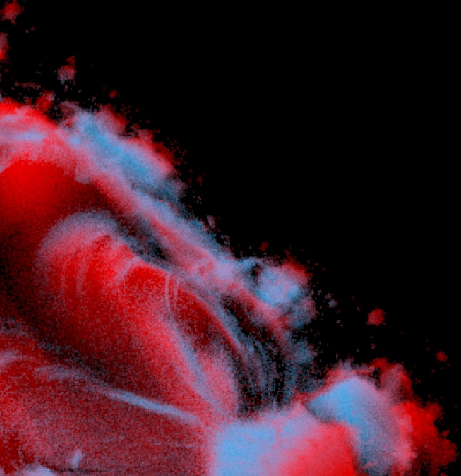
Step Size: 0.1
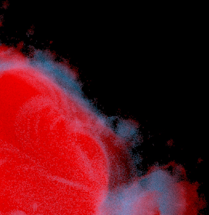
Step Size: 0.6
Another factor which has an impact on the render times is the size and shape of the bounding geometry. Set it as tight as possible, because unnecessarily large bounding shapes will waste rendering power on an empty space. Another option which has an impact on the refinement of the fractals is the Max Iterations parameter on our OSL Mandelbulb nodes. Try setting it as high as visually needed, but not too high as it has quite an impact on render times.
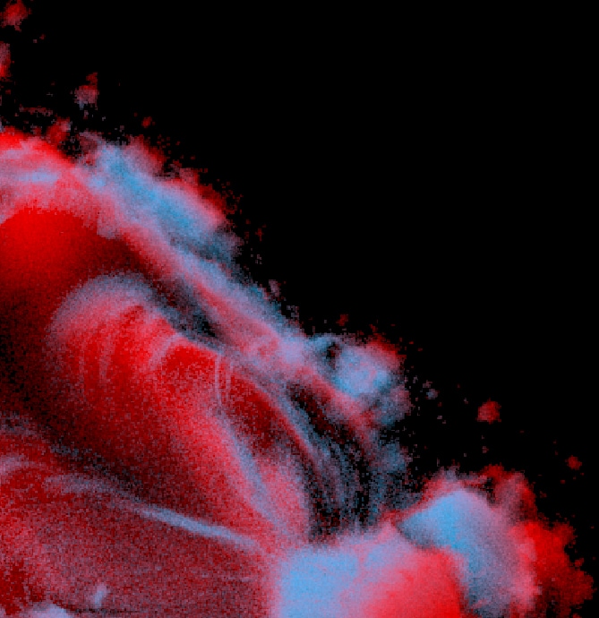
Iterations: 150
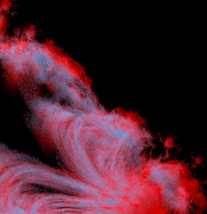
Iterations: 10
There are also standard Arnold ROP quality settings. Note that when rendering emissive fractals it is a good idea to split the render into two passes - one for emissive lighting and one for scene lighting. This is because they will need different combinations of settings and rendering them together will be slower than rendering them separately.
Close
Join the community
Need help? With in-depth documentation, a responsive development team and a supportive community ready to answer your questions, you’ll be on your way to creating amazing things.
Need help? We have in-depth documentation, a responsive development team, and a supportive community ready to answer your questions.
Get Arnold
Ready to get your hands on the best-looking 3D renderer? Try HtoA for 30 days free.
