Sheet metal design software
See how the Autodesk Product Design & Manufacturing Collection streamlines sheet metal fabrication and design and allows you to design, test, document and fabricate in a single integrated tool.
See how the Autodesk Product Design & Manufacturing Collection streamlines sheet metal fabrication and design and allows you to design, test, document and fabricate in a single integrated tool.
With the visualisation efficiencies built into the Product Design & Manufacturing Collection, sheet metal designers can easily design in 3D, then unfold into 2D for production.

The Collection software includes tools that allow you to simply create a pattern of a feature with unequal spacing and edit any value so the pattern will adapt accordingly.

With the Product Design & Manufacturing Collection, you can work with imported models and easily reorient them into your part file.

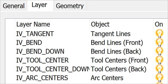
When exporting a flat pattern, the software allows you to create additional layers by default rather than editing the DWG/DXF later.

Tools inside of the Product Design & Manufacturing Collection allow you to quickly document the sheet metal bending process for fabrication.
A flange is a common sheet metal feature, which consists of a bend connected to stationary face, along a straight edge.
Bend calculations ensure the correct length is calculated when a sheet metal design is manufactured flat, then bent into its finished state based on a K-Factor.
Gauge tables define the thickness of sheet metal. There are several gauge tables depending on the material of the sheet metal, which specify the thickness for both inches and millimetres.
The Product Design & Manufacturing Collection drives efficiency into the entire sheet metal design process. Work with design, documentation and product simulation tools. Collaborate freely across teams. Increase design accuracy and streamline your entire workflow.

Pressurised water mixed with abrasives can cut through stainless steel, Inconel, titanium, aluminium, tool steel, ceramics, granite and armour plate, with a clean edge finish.
A gas laser, such as a CO2, is transmitted through a beam, guided by mirrors and directed at the material at an extremely high level of precision.
The plasma process uses electrically conductive gas to transfer energy from a torch to the material being cut. Developed for metals that could not be flame cut, such as stainless steel, aluminium and copper.
Fusion 360 is a next-generation, cloud-connected CAD, CAM and CAE software that can take you from concept to production.
Design, test, document and fabricate in a single integrated tool.
Access your data anywhere on any device to stay connected throughout the product development process.
Use the single flange tool to make just about anything, including base flanges, edge flanges, miter flanges and contour flanges.
After market bumpers designed with Fusion 360
Fusion 360 users from around the world competed in designing the best sheet metal bumper for a truck. Designs were bent, folded and cut into the most unique sheet metal bumpers out in the market.
To reduce scrap and increase efficiency, work pieces need to be "nested" onto the stock. Use the nesting utility in Inventor to optimise yield from flat raw material.
Learn the features and workflows needed for brake press sheet metal design in this Autodesk University online class.
Learn the foundational concepts of sheet metal design and manufacturing in Fusion 360 through these learning courses.
Learn how to create parametric cardboard packaging using sheet metal tools.
Learn how Autodesk Inventor software makes sheet metal design simpler and easier. Follow the tutorial to make a simple sheet metal part, use the flange feature, create a flat pattern and more.
Follow along to see how to complete a sheet metal manufacturing workflow, from design importing and application of material data, to performing an optimal nesting process and finishing with a CNC programme to be used for manufacturing.
Review this professional tutorial for best-practice tips for using Inventor software for sheet metal design.
The Product Design & Manufacturing Collection software includes direct editing and advanced surface modelling features designed to dramatically reduce the time typically necessary for high-volume design production. Validate 3D digital models as you design without needing a prototype. Stress-test and optimise in one integrated design environment. Plus, built-in sheet-metal specific commands streamline work on both folded and unfolded models.
Inventor simplifies calculating bend allowance and offers the flexibility to see bending results specific to the data you have. While the default K-Factor of 0.44 is automatically built into the software, you can access the integrated editor in Inventor to create and edit bend tables.
Fusion 360, included in the Product Design & Manufacturing Collection, streamlines the deformation-based sheet metal forming process. The software simplifies simulating sheet metal forming with easy setup of loading conditions, contact conditions, fixes and displacement boundary conditions and non-linear material properties.
Files from other CAD systems can be imported for use in Inventor (part of the Product Design & Manufacturing Collection) and exported to other CAD system formats.