Inventor
Inventor
Use Inventor® 3D CAD modeling software for product and mechanical design. Learn about the Inventor modeling, design, simulation, and rendering features.
Use Inventor® 3D CAD modeling software for product and mechanical design. Learn about the Inventor modeling, design, simulation, and rendering features.
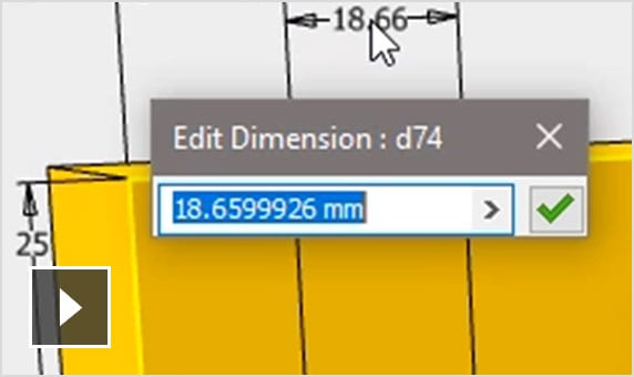
Focus on design as you create and edit your 3D models with an intuitive user interface. (video: 2:33 min.)
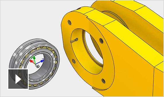
See how your design will go together and perform at the assembly level. (video: 2:43 min.)
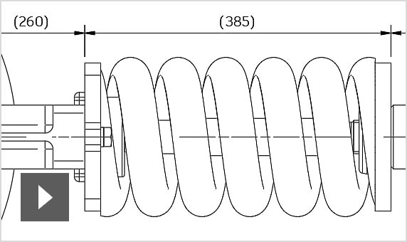
Quickly create clear, accurate, detailed drawings for manufacturing. (video: 3:07 min.)
Collaborate on your models or designs online. Anyone can review and comment on shared views in the Autodesk viewer. (video: 2:23 min.)
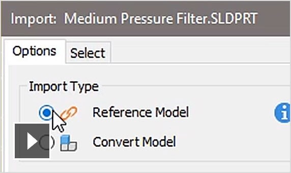
Maintain an associative link to non-native CAD data. (video: 1:57 min.)
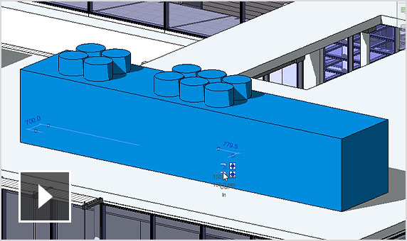
Convert configurable 3D CAD models into BIM objects. (video: 2:27 min.)
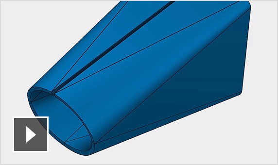
Design and prepare complex sheet metal products for manufacturing. (video: 1:42 min.)
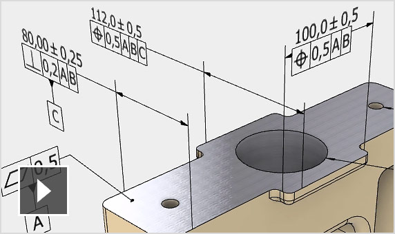
Include manufacturing information in your 3D model for downstream applications. (video: 2:10 min.)
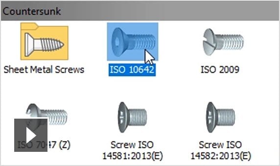
Choose your standard components from a comprehensive customizable library. (video: 2:15 min.)
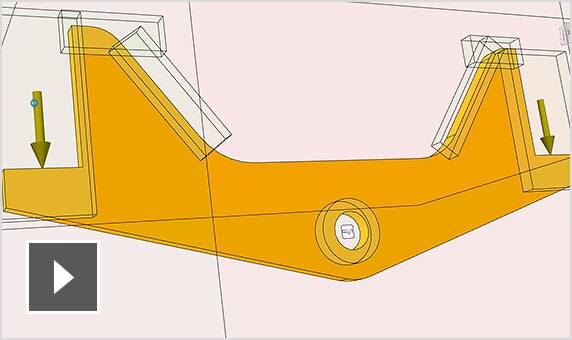
Create and evaluate high-performing design options in minutes. (video: 2:16 min.)
Use the right modeling tool for every job with parametric, freeform, and direct modeling tools.
Use easy push/pull controls to move, rotate, resize, or scale features from imported geometries.
Freely sculpt the shape of your design by moving points, edges, and faces.
Open DWG™ files directly inside Inventor as the basis for your 3D model.
Use built-in calculators to inform the design of common joints such as welds, clamps, and press fits.
Use a combination of automated tools and full-control design functions in Inventor to build tube and pipe runs.
Integrate your electronics and mechanical designs into a single, complete definition of your product.
Use easy push/pull controls to move, rotate, resize, or scale features from imported geometries.
Apply forces to evaluate the motion, speed, and acceleration of your design.
Run quick checks on parts or perform in-depth analysis of the entire product at any stage.
Use exploded views and animations of complex assemblies in product documentation, manuals, and assembly instructions.